ast Year's Model
Field Day 2004 rolled around,and I didn't want to deal with the
electrically well behaved yet physically awkward portable quad I'd done up
for 2003. I did some brainstorming and some juggling of numbers,and came
up with a really quick and dirty design based on Radio Shack 6' collapsable
whip antennas. Antenna dimensions were culled from the wideband design
described in Larry Cebik W4RNL's "2X3=6" article in the February,2000
QST
| Bill of Materials |
|---|
| 1 | 10' length of 1/2" PVC pipe |
| 2 | 1/2" PVC end caps |
| 1 | 1/2" PVC Tee fitting |
| 1 | 6"x8" printed circuit board |
| 3 | 1" stainless steel U-bolts with nuts and washers |
| 12 | 3/8" U-bolts with hardware |
| 6 | Radio Shack 6' collapsable whip antennas |
| 1 | 10' length of RG-8x with attached SO-239 connector |
| 3 | 8-32 x 2" machine screws with washers and wingnuts |
| 2 | 2" stainless steel hose clamps |
I cut the PC board into three 2"x8" strips. Each strip was then drilled
for one 1" U-bolt lengthwise and 4 3/8" U-bolts crosswise down the center
line. I cut a furrow across one strip,breaking the copper cladding into
two pieces; this strip was used for the driven element. I clamped the
collapsable whips to the strips,one whip through two of the small U-bolts.
(This would all make a great deal more sense if I had pictures or drawings,
I know.) The PVC pipe I cut into two 3' and two 2' sections.
The 3' sections went into the through ends of the Tee fitting,and are
held in place with the machine screws,washers and wingnuts. One of the
shorter pieces of pipe went into the butt end of the Tee and is also held by
a machine screw and wingnut; the short piece is used to secure the antenna
to a mast with the hose clamps.
I slid the large U-bolts over the long PVC pipe,positioning them as per
the spacings the modelling softare coughed up,tightened down the U-bolts
and extended the whips to the lengths indicated by the model and marked with
indelible marker. Hey presto! I had a fairly cheap,eminently portable 6
meter yagi. Up at 20' on a portable mast at Indian Rocks Beach,FL,it
worked quite well for Field Day. Unfortunately I don't seem to have kept
any pictures of the rather hideous kludge.
Time to Reinvent the Wheel,only Round This Time
Fast forward to spring of 2005. I've been thinking about how to
improve
the antenna,and make it more portable. I came across an article on
building a take-apart portable HF vertical by Phil Salas AD5X,in the
July,2002 QST. The article had some clever ideas about how to connect
the
antenna's various bits together; the thing I latched onto was the notion
of
using 1/8" pipe nipples to provide threaded fittings on the Radio Shack
collapsable whips. Turns out that the whip almost fits inside a pipe
nipple; a bit of redrilling with a 9/32" bit is all that's needed. The
article said to scrape or grind off the chrome plating and solder the nipple
to the whip end. That's just what I was looking for to get rid of the
rather ad hoc PC boards and U-bolts arrangement. The whips will also
be cut down to their final lengths so that any guesswork and measurement
will no longer be necessary at assembly time.
A trip to Home Depot (and some last minute rethinking of how to mate the
elements to the boom sections) netted a stack of pipe nipples,couplings and
adapters. Long nipples with couplings on each end will be secured to the
boom sections for the director and reflector; a cross fitting with a pair of
1/2" to 1/8" plug adapters epoxied into two ends will provide attachment
points for the driven element. This will result in an antenna that will
knock down to a much more portable package,and go together much more
quickly.
Once I've modified- well,torn apart and reconstructed is more accurate-
the 3 element portable yagi as described,I may well carry through and
build a 4 element version; all it would take is another hunk of PVC
pipe,some more fittings and another pair of those Radio Shack whips; the
resulting antenna would be just about as portable and only a little
more awkward to handle assembled. That's probably the practical upper
limit on what one could accomplish on a 1/2" PVC boom; moving to 5
elements would likely necessitate going to EMT or aluminum boom
sections. Maybe that'll be the project for 2006.
The WA4UF Portable 6 Meter Yagi,2005 Edition
The goal was to build a 6 meter Yagi that would collapse down into nothing
larger than 4',so as to clear the trunk lid opening on a 2001 Honda Accord.
It had to assemble and disassemble quickly,and pack up with a minimum of
loose bits. Here's what I came up with.
| Bill of Materials |
|---|
| 1 | 10' length of 1/2" PVC pipe |
| 2 | 1/2" PVC end caps |
| 1 | 1/2" PVC cross fitting |
| 6 | Radio Shack 6' collapsable whip antennas |
| 1 | 10' length of RG-8x with attached SO-239 connector |
| 2 | large alligator clips |
| 2 | 8-32 x 2" machine screws with washers and wingnuts |
| 1 | RCA TV antenna boom-mast clamp |
| 3 | 1/8" x 1-1/2" brass pipe nipples |
| 6 | 1/8" x 3/4" ("close") brass pipe nipples |
| 6 | 1/8" brass female pipe couplings |
| 2 | 1/2" x 1/8" brass male pipe to fip hex bushings |
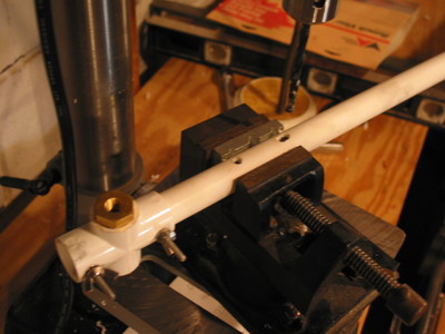
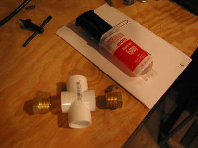 First thing to do is prepare the center fitting,where the boom sections and driven element will attach. Trim about 1/4" off
of opposite legs of the cross fitting. Using a round file,widen the
openings until the bushings just fit. Mix up a small batch of 5 minute
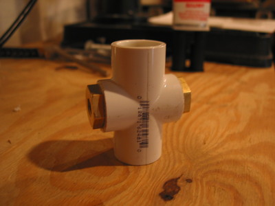
epoxy. Epoxy the two bushings into the shortened legs of the cross fitting. First thing to do is prepare the center fitting,where the boom sections and driven element will attach. Trim about 1/4" off
of opposite legs of the cross fitting. Using a round file,widen the
openings until the bushings just fit. Mix up a small batch of 5 minute
epoxy. Epoxy the two bushings into the shortened legs of the cross fitting.
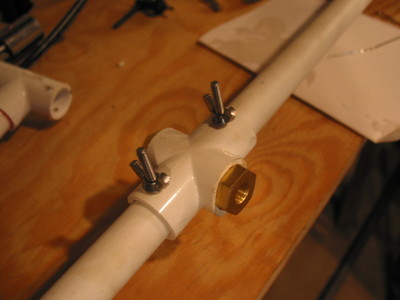 Cut the PVC pipe in half,and insert one piece into
one unaltered leg of the cross fitting. Drill through the fitting and pipe
with an 11/64" bit,and install a machine screw,washer and wingnut to hold
it all together. Repeat with the other piece of pipe and the last leg of
the cross fitting. Cut the PVC pipe in half,and insert one piece into
one unaltered leg of the cross fitting. Drill through the fitting and pipe
with an 11/64" bit,and install a machine screw,washer and wingnut to hold
it all together. Repeat with the other piece of pipe and the last leg of
the cross fitting.
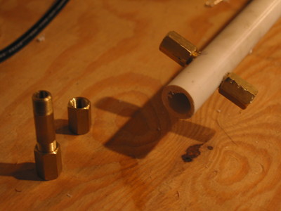 Now it's time to measure and mark for mounting the
director and reflector. As in last year's model,the dimensions came from
the wideband design in the "2X3=6" article. Measure 40-3/4" from the center
of the cross fitting and mark on the pipe; this is where the reflector will
attach. Measure 33-1/2" from the center of the cross fitting and mark on
the other pipe; the director will go here. Disassemble the pipes from the
cross fitting. Drill through each pipe with a 27/64" bit. Now it's time to measure and mark for mounting the
director and reflector. As in last year's model,the dimensions came from
the wideband design in the "2X3=6" article. Measure 40-3/4" from the center
of the cross fitting and mark on the pipe; this is where the reflector will
attach. Measure 33-1/2" from the center of the cross fitting and mark on
the other pipe; the director will go here. Disassemble the pipes from the
cross fitting. Drill through each pipe with a 27/64" bit.
Insert a 1/8" x 1-1/2" pipe nipple through one of the holes just
drilled
and thread a 1/8" pipe coupling on each end. Using a pair of
wrenches,tighten both couplings simultaneously until you simply can't
tighten them
any more. Repeat for the other hole. Mix up another small batch of
epoxy
and glue the nipples to the boom sections. When the epoxy has dried,cut
each pipe off just beyond the epoxied-in fittings,and glue a pipe cap to
each cut end.
 The last bit of boom work is to install the
boom-mast clamp. Drill a pair of 1/8" holes through the longer boom
section,about 3 " from the cross fitting. "Wobble" the bit so that one set
of holes is slightly elongated; this makes it easier to insert the clamp.
Install the clamp so that the serrated round cutouts on the clamp fitting
face the U-bolt. If you're liable to do a lot of FM work,drill a second
set of clamp mounting holes an inch or two further down the boom section 90
degrees around the pipe from the first set of clamp mounting holes. Then
you can mount the antenna vertically or horizontally. As always,if you're
going vertical,plan on using a nonmetallic mast so as not to affect the
antenna's operation. The last bit of boom work is to install the
boom-mast clamp. Drill a pair of 1/8" holes through the longer boom
section,about 3 " from the cross fitting. "Wobble" the bit so that one set
of holes is slightly elongated; this makes it easier to insert the clamp.
Install the clamp so that the serrated round cutouts on the clamp fitting
face the U-bolt. If you're liable to do a lot of FM work,drill a second
set of clamp mounting holes an inch or two further down the boom section 90
degrees around the pipe from the first set of clamp mounting holes. Then
you can mount the antenna vertically or horizontally. As always,if you're
going vertical,plan on using a nonmetallic mast so as not to affect the
antenna's operation. 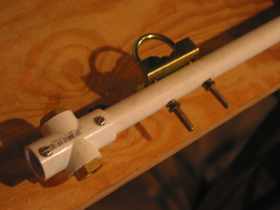
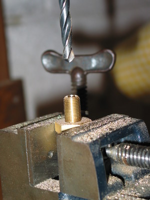 The elements must now be prepared. Using coarse
sandpaper or a small file,take the chrome plating off the end 1" of each of
the six 72" collapsable whips. As in the July,2002 QST article,drill out
each of the short pipe nipples with a 9/32" bit. Slip each nipple over the
end of a whip and solder the whip and nipple together. A propane torch or a
really large soldering iron or gun will be necessary here. The elements must now be prepared. Using coarse
sandpaper or a small file,take the chrome plating off the end 1" of each of
the six 72" collapsable whips. As in the July,2002 QST article,drill out
each of the short pipe nipples with a 9/32" bit. Slip each nipple over the
end of a whip and solder the whip and nipple together. A propane torch or a
really large soldering iron or gun will be necessary here. 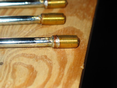
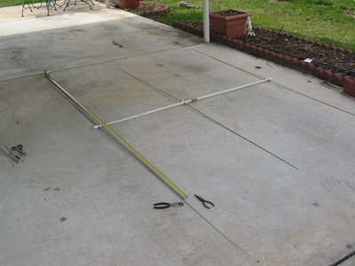 Assemble
the antenna on a large flat surface; the driveway works well. Screw an
element into each of the six threaded fittings and extend the whips all
the way. Measure out from the center of the boom and mark each
telescoping whip. Measure 58-1/2" on each side of the reflector,54" on
each side of the driven element,and 48" on each side of the director.
Cut off each whip approximately 1" beyond the mark,flatten the end of
the whip back to the mark,then roll up the flattened section with
needlenose pliers. For a more finished appearance,build up a blob of
epoxy on each rolled up end. Mark each element as being part of the
director,driven element or reflector,and mark the director and reflector
ends of the boom as appropriate before disassembling the antenna. Assemble
the antenna on a large flat surface; the driveway works well. Screw an
element into each of the six threaded fittings and extend the whips all
the way. Measure out from the center of the boom and mark each
telescoping whip. Measure 58-1/2" on each side of the reflector,54" on
each side of the driven element,and 48" on each side of the director.
Cut off each whip approximately 1" beyond the mark,flatten the end of
the whip back to the mark,then roll up the flattened section with
needlenose pliers. For a more finished appearance,build up a blob of
epoxy on each rolled up end. Mark each element as being part of the
director,driven element or reflector,and mark the director and reflector
ends of the boom as appropriate before disassembling the antenna.
The antenna needs a feedline,and I went for quick-and-dirty here. I
installed a pair of large alligator clips on the stripped leads of one end
of a length of RG-8X; the other end had an SO-239 connector installed. I
carefully coiled 5 turns of about 5" diameter close to the alligator clips
and bound up the resulting RF choke with vynyl electrical tape and cable
ties. Each alligator clip was then clamped around one side of the driven
element,as close to the fittings as possible.
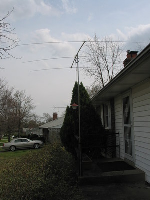 The completed antenna was hoisted up on a 10'
piece of EMT in the back yard and a couple of local 6 meter QSOs completed.
Quick transmit tests verified less than 2:1 SWR across the usual SSB section
of the band; FM tests were not made due to lack of time. Later on I moved
the antenna out front by velcroing the EMT to the handrail on the front
steps,as seen here. The Yagi broke
down into a bundle 42" long and about 2" in diameter,along with a coil of
feedline. The results are most satisfactory; a wideband,easily
transported,easily assembled antenna was assembled for not a lot of money
and just a morning's worth of time.
Addendum 06-15-05 - First field use
The antenna got its first "real" use over Memorial Day weekend,during
the Geowoodstock III geocaching
event. I had the antenna most of the way up a 24' sectional mast along with
a 4el 2m Yagi and one end of a 20m double Zepp. Band conditions were less
than favorable,so I didn't make but one 6m contact,but the antenna went
together and went up pretty much as intended. Coming back *down* however,I
managed to snag and bend both halves of the director on a tree. The bends
occurred where the collapsable sections had been pinched and bent by the
little U-bolts on the "last year's model" described at the head of the
article. I straightened them as well as I could,but both pieces are now
cracked and very delicate.
This has lead to a rethinking and redesign,and the ordering of 18' each
of 3/8" aluminum tube and 1/4" aluminum rod from Texas Towers. I had considered
replacing the Radio Shack parts with collapsable bits from either MFJ or W3FF (The BuddiPole folks),but I'd have
gone way over budget. As it is,the shipping from Texas Towers cost as much
as the aluminum tubing itself. That irked me,but I still spent less than I
would have buying inferior tubing from the local Ace. When the aluminum
arrives,I'll be building new elements. The 3/8" tubing will be cut into 3'
lengths and threaded on both ends. One end will screw into the fittings on
the boom. The other will get a compression fitting that will clamp down on
the 1/4" rods,which will also be cut into 3' lengths and telescoped into
the tubing sections. Thus I'll have much more durable elements,which will
still meet my goal of nothing being longer than the trunk openings on the
cars.
Addendum 01-08-07
I've lugged the antenna to Mom's,to the inlaws' cabin,and to the beach
several times; the telescoping rod and tubing elements have held up quite
well. Sometimes my ambition gets the better of me and I think I'll have to
try a 4 element version,but the boom would have to be rethought; 1/2" PVC's
not quite rigid enough to manage 8 or 10 feet unsupported.
The surviving four sections of 6' collapsable antenna currently reside in
the junk pile. At some point I might try mating them with a new boom made
from 1' sections of PVC for use as a 2 element beam which will break down
small enough to stuff in a backpack for hilltopping. Stay tuned!
© 2005 Bruce H. McIntosh WA4UF. Permission granted to print and
distribute to the Amateur Radio community. | 
