How or why does a Quad
(or any other
antenna) develop gain?
With any antenna,
gain only occurs
from compression of
radiation into a
narrower area. One
analogy is a
balloon. If we
half-fill a
perfectly round
balloon with a given
volume of air and
squeeze it, the
balloon extends out
in other directions.
An antenna works in
a similar manner.
Our transmitter's
power fills the
aether around the
antenna, and we
modify or build the antenna
in a way that causes
transmitter power to
"fill less space" in
unwanted directions. While the
total power radiated
does not increase
(the net radiated
power can never be
more than the
applied power),
power in certain
directions or areas
becomes more
intense. This
assumes of course we
don't do something
foolish while
squeezing the
pattern, causing
transmitter power to
be wasted as
heat.
We do something
to force radiation
into a small area of
space without adding
significant
additional heat
loss, and we
suddenly have
"gain". Gain is
always defined a
ratio of the antenna
under test to some known
pattern or radiator, commonly a
fictitious
theoretical isotropic
radiator (commonly in a model),
or dealing
with real
measurements we
almost always use
a reference dipole
at the same mean
height.
I have to add a
word of caution at
this point. The dipole is
a
basic building block
of many antennas.
Let's dispel a
common
gain misconception
about the gain
differences
between dipoles and
isotropic radiators. A dipole does
not
have 2.15 dB gain over
an isotropic
radiator when the
dipole is placed
over earth. At
optimum heights, a common 1/2 wave dipole
actually has about 8.5 dB gain
over an isotropic
radiator! Always
remember this when
you see antenna
models over earth
that give an
antenna's gain in dBi.
If
a
model over earth
shows a "gain" of
about 8.5
dBi, the model
effectively has the
same gain as a
dipole at optimum
height over typical
earth! We cannot
add 2.15 dB to the
isotropic gain to
get the dBi gain
unless both antennas are in
free-space!
The
instant the earth is
involved in a model
or measurement, the
2.15 dB rule flies out
the window. The "add
2.15 dB" rule
works in freespace
when comparing
antennas in
freespace, but not
when the antenna
is over earth.
Why? Because there
is no such thing
as isotropic
radiation over
earth! Let's look at a
dipole in freespace.
Freespace gain of a
low-loss 40 meter
dipole is 2.13 dBi.
This gain occurs
because the dipole
compresses the
pattern into a
"figure 8". In some
directions (directly
off the ends of the
dipole) there is
virtually no
radiation at all.
Now let's put
the
same antenna model over real
earth at 1/2 wavelength
above ground:

We see now the
gain is 8.09 dBi.
This is because the
earth compresses the
pattern vertically.
Gain would actually
be more than 8.1
dBi, except the
model is for fairly
low conductivity
earth. There are
actually 0.67 dB of
losses included in
the model, most of
which relate to the
earth below the
antenna! These
losses would mostly
go away if we
installed a good
ground screen below the antenna.
We will not do
that for now,
instead we
will assume
normal dirt without
any large reflector,
large counterpoise,
ground screen, or radial
system to shield the
antenna fields from
the lossy
earth below the
antenna.
The quad obtains
its gain from
stacking two bent
half-length
dipoles 1/4 wave
apart. Watch and see
how this works!
Stacking Gain and
Dipoles
Let's look at two
lossless full-size
dipoles stacked 1/4
wave apart in
freespace:
1/4 wavelength is
the stacking
distance of a quad
element.
We now have 3.22
dBi gain. Looking
back, the
original low-loss
dipole in freespace
had 2.13 dBi gain.
This means the net
gain of two full-size stacked dipoles
in freespace is
3.22-2.13 = 1.09 dB
more than a single
dipole. This isn't
much gain, and it is
an optimum
condition (full
length elements in
freespace) with 1/4
wavelength stacking
distance!
Now let's look at
the same dipoles
over earth, at the
same mean height as
the original dipole:
We now have 8.37
dBi gain. If we
look back, we see a
single dipole had
8.09 dBi gain! The
net gain from
stacking two full-size dipoles 1/4
wave apart over
earth is only 0.28
dB! Peak gain wave
angle is 27 degrees,
a meaningless 1
degree lower than
the single dipole.
Since the earth
tries to force an
overhead null, and
the stacked
dipole system tries to do
the same, at least
one of the two
effects or systems trying to
force the overhead
null cannot give the
full gain advantage.
| Rule:
To increase
gain, the
antenna has to
force a null in
a direction or
angle that
previously had
significant
energy. |
The Quad Element
Now let's look at
a lossless quad loop
in space:

The quad "creates
gain" by acting like
two 1/2 size
end-loaded dipoles
stacked one above
the other with 1/4
wavelength spacing.
We now have 3.27
dBi gain, or 1.13 dB
more gain than a
dipole in freespace.
This is a perfect
lossless quad
element under ideal
conditions.
Now let's look at
the quad with copper
losses, over real
earth at the same
mean height as the
dipole:
We now have 8.08
dBi gain. The dipole
at the same height
over the same earth
with the same size
wire had 8.09 dBi
gain. The quad
element has 0.01 dB
LESS gain than a
dipole with the same
wire size at the
same mean height.
Peak radiation
occurs at 27
degrees, only one
degree less than a
dipole!
The quad element
has increased the
H-plane beamwidth
very slightly, and
decreased E-plane
beamwidth very
slightly.
Now in fairness
we could have placed
the quad element at
a height where the
earth tries to force
a null into an area
where the quad has
significant energy.
Even so, the quad's
gain advantage can
never be more than
the ideal condition
of freespace, or
just over 1 dB. In
reality, the quad
advantage is nearly
always less than 1
dBd. It's fair to
say gain is anything
from slightly
negative, to about 1
dB maximum.
Another idea or
claim is
the vertical sides
of the quad, with
their wide spacing,
will act like a "leaky transmission
line" and allow
vertical
polarization
response
simultaneously with
the normal
horizontally
polarized response. The thing
that kills this idea
are currents in
the vertical wires.
Radiation is
caused by charge
acceleration, and
this means radiation
is proportional to
current level over
distance. It is the
ampere-feet that
matters. For the
horizontally
polarized quad
element, A and B are
current minimums.
The side lengths
of A and B are
comprised of two
1/8th wave long
vertical elements
out-of-phase. While
side A and side B,
like sides C and D,
are each a
physical total
of
1/4 wave, the
currents at A and B
are out-of-phase.
This means we have
two vertical
currents on each
side flowing
opposite directions.
The quad has
radiation
cancellation from:
1.) Each side
being short
effective lengths
and low current,
reducing ampere-feet
and the amount of
radiation
2.) Each side
being out-of-phase
with each other,
canceling radiation
3.) The upper
and lower halves of
each side being
out-of-phase,
further canceling
radiation
If we wanted to
do a design that
prevents the
vertical sides from
radiating, the
horizontal quad
element is an ideal
design! C and D
essentially do all
of the radiating.
What does the
above show us?
- Maximum gain
difference between
a quad element and
dipole element
occurs in
freespace, and
that gain
difference is
about 1.13 dB.
- Radiation
angle of a quad is
insignificantly
different than
that of a dipole.
- The quad
element does
NOT have
2 dB gain over a
dipole at any
height. In truth
the quad can have
loss and is
actually never
significantly
better than a
dipole when over
earth!
- The
horizontally
polarized quad
does
not radiate from
the vertical sides, and as
a result does not
have a mixture of
polarizations or
"diversity".
We have just
dispelled four
popular quad
myths; that a quad
element has 2 db
gain over a dipole,
that a quad is
insensitive to
height,
that a quad has
multiple
polarizations, and that a quad has
much lower radiation
angle than a dipole.
Two Element Quad
vs. Yagi
Let's look at a
two element quad
compared to a two
element yagi at
various heights.
The pattern of
left is a
two-element 20-meter
quad 35 feet high
(1/2 wave high) that
is a Handbook
design. This quad
has #12 copper
elements.
It has a gain of
11.46 dBi, which is
about 3 to 3.5 dBd
(dB over dipole) gain. This is,
unremarkably, about what
we would expect from
any two-element
end-fire array. No
magic here!

The pattern of a
two-element yagi at
the same boom-height
as the quad, with
the same amount of
copper in the
elements, shows
11.25 dBi gain or
2.7-3.3 dBd (dB over
dipole) gain. There
is 0.2 db difference
between the quad and
yagi using wire
elements with the
same total copper
weight at the same
height.
Some adjustment
of the reflector
from Handbook
dimensions improves
F/B ratio. Peak F/B
ratio is now over 30
dB.
Unfortunately
gain has dropped to
11.05 dBi, or about
2.5 to 3 dB over a
dipole. Once again,
this is expected. If
we optimize F/B
ratio we can expect
lower gain from any
parasitic array.
A 2-element yagi
with one-inch
diameter tubing
elements has about
the same gain as a
2-element quad
optimized for F/B
ratio. They both
have the same exact
wave angle
dispelling the wave
angle myth.
The 2-element
yagi has slightly
less F/B ratio,
which will slightly
impact receiving. If
we have unwanted
interference or
noise from the rear
of the antenna the
quad will have a
slight advantage.
As a matter of
fact if we tune the
yagi as a parasitic
director instead of
reflector, we can
shorten the boom to
6 feet, less than
half the boom length
of the quad, and
have about the same
performance!
The clear answer
is a two-element
quad, all things
equal, sometimes
offers a slight
receiving advantage
over the 2-element
yagi. This would
occur if we have
substantial noise or
unwanted signals
coming from the rear
direction. The more
elements we add, the
less difference in
F/B we have. As a
matter of fact a
3-element yagi and
3-element quad are
essentially equal in
gain and F/B ratio.
There is virtually
no difference
between them.
Why is there a
big long argument?
Because the antennas
are so close in
performance any real
differences are
mostly due to
construction errors
rather than the
antenna being a quad
or a yagi!! Use
whichever one you
like.
My own 40 meter
yagis, with a 0.4 WL
boom, model in
freespace to have
9.41 dBi gain at
optimum gain
frequency.
I chose however
to give up a few
tenths of a dB gain
for higher F/B
ratio, bringing them
down to just over 9
dBi gain and 28 dB
F/B.
Combinations of
settings are
endless, and I'm
sure there are some
better than this,
but in reality there
is very little
difference between
the quad and yagi
antennas. The real
difference is mostly
in user preference
for mechanical
attributes.
Keeping it
all honest:
Lowering of wave
angle? Myth.
2 dB
more gain? Myth.
Better receiving?
Some truth to that,
but the change is
small and occurs
only under certain
conditions.
Where did the 2
dB gain over a
dipole come from?
If we look at
antenna books and
articles about quad
antennas, we will
often find
references to quad
antennas having 2 dB
gain over a
comparable boom
length yagi antenna.
The statement often
made is a single
quad element has 2
dB gain over a
dipole, and that 2
dB gain difference
carries over into
arrays of quad
elements. If we
actually model or
build antennas we
find the gain
difference between a
quad element and
dipole is always
less than 1.2 dB,
and at certain
heights a quad
element has less
gain than a dipole.
This makes perfect
logical sense. We
know a quad element
is really two
dipoles bent so the
ends connect, with
1/4 wave spatial
separation between
current maximums.
This forms a stacked
array (broadside
array) of two
half-size end-loaded
dipoles with 1/4
wave spacing. There
is a slight increase
in
E-plane beamwidth
by shortening dipole
lengths, this tends
to reduce gain and
broadens the azimuth
beamwidth of a
horizontally
polarized antenna.
The stacking gain
(broadside gain)
tends to slightly
compress the H-plane
beamwidth of the
quad. This effect
slightly increases
gain. We can look at
a graph of broadside
gain and see the
theoretical maximum
stacking gain, even
if we do not shorten
the radiating area
by folding or
abruptly bending the
ends.
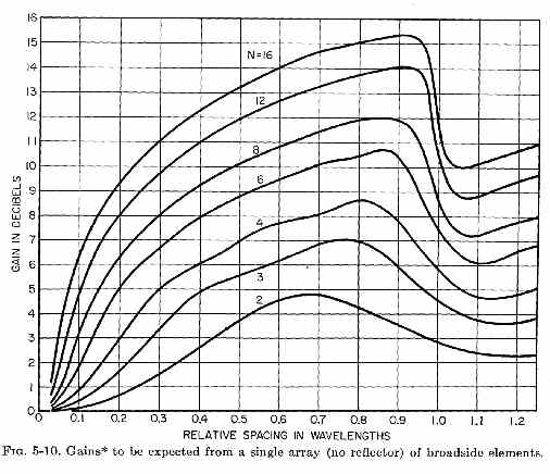
This is no
coincidence I
invented, or
anything new. The
graph above is from
a 1950's antenna
textbook! We can
clearly see the gain
of two broadside
elements 1/4 wave
apart is barely over
1 dB, and this is
what the antenna
models using modern
software show. The
quad at very best
barely has 1 dB gain
over a dipole, and
at worse has loss.
The high current
areas just do not
have enough spatial
separation to
provide much gain.
Where did the 2
dB come from then?
The first reference
I can find to 2 dB
gain came in 1952
from Mushiake and
Adachi of Tohoku
University in Japan.
They calculated the
gain of a large
circular
full wave loop as
about 2 dBd (dBd =
db over dipole).
These figures were
based on a single
circular loop far
from ground, not on
a square quad loops.
The diameter of a
1-wavelength
circumference circle
is .318 wavelength.
We see the
theoretical maximum
gain is well under 2
dB (even if the
elements were
dipoles stacked .318
wl apart) and
models confirm this.
The gain of a
circular loop is
shown below:
We see the gain
of a lossless
circular loop is
3.46 dBi, or 1.32
dBd. This is nowhere
near the 2 dB put
forth by Mushiake
and Adachi in 1952.
The 1.32 dB NEC
model does closely
agree with the
1950's engineering
textbook. The
average or mean
separation of the
current maximum
areas in a full wave
circle is about .275
wavelengths, which
corresponds to about
1.3 dB gain. Once
again the modern
NEC-based model and
older engineer
textbooks closely
agree.
It's my belief
these measurements
carried over into
amateur publications
and were repeated
and exaggerated over
the years by
well-intentioned but
not-so-accurate
amateurs.
The first source
of amateur
measurements I can
find were by Lindsey
ex-W0HTH (now W7ZQ)
on 440 MHz. However
derived, these
numbers are
obviously flawed. 2
db is clearly beyond
the highest
theoretical maximum
ever predicted for
circular elements,
and his elements
were square! Such a
mistake is easy to
make using measured
pattern to estimate
gain, which is the
method Lindsey used.
The problem is
once bad information
is printed the
misinformation stays in
print. We can't go
back and erase the
May 1968 QST, nor
can we erase other publications that
copied and reprinted
the exaggerated gain
claims.
The original and
copied 2 dBd gain
claims will
remain in books and
archives through eternity.
They
will reappear as
people read old
texts and search
archives, and the
reappearance will
fuel the argument
that an impossibly
flawed gain claim
is
something "open for debate"
because "the
argument would not
go on for years if
the claim did not
have merit".
Sorry, but the
argument continues
only because it once
appeared in print
and was copied
several places. It
does not continue
because the original
exaggerated claims
have technical
merit.
Noise and Quads
Some claim a quad
element has less
noise than a dipole.
There is a limited amount of
truth to that idea,
but not because the
antenna is dc
grounded!
DC is not RF.
Noise is not DC. The
receiver already
filters all the
out-of-band noise
out. By definition
we cannot filter
noise except with
selectivity, and
that would require
the antenna be
narrower bandwidth
than the receiver
filters! We know
that isn't true.
The blunt ends of a
quad at the high
impedance voltage
points, rather than
the sharp projected
tips of a yagi, can
reduce the effects
of precipitation
static...but that
would only occur in
inclement weather
when corona is
present at element
tips. As a matter of
fact the quad was
originally
popularized just for
this reason, to
minimize corona
under extreme
element voltage
conditions. Oddly,
this effect has
nothing to do with
dc grounding! It
is only related to
the blunt ends where
the high impedances
were present, and
the fact those
blunted ends
do not protrude out
into open space!
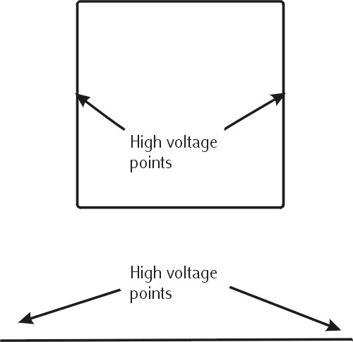
The area most
responsive to noise
caused by corona
discharge is in the
center of the blunt
sides of a
horizontally
polarized cubical
quad. This is
because the highest
impedance point in
the antenna is at
the middle of the
blunt sides. The
sides are neither
the highest point in
height (where storm
static electric
field is most
intense) nor are
there sharp
protruding points.
The area most
sensitive to noise
caused by corona
discharge is at the
very tips of a
"dipole" style
element.
Unfortunately this
is the highest
impedance area, so
the very high
impedance RF noise
caused by corona
leakage is matched
to the receiver
system the best. The
tips protrude into
empty space away
from everything
else, and are often
at or near the
highest point in the
antenna. This is
where electric field
gradient is
strongest and corona
most likely to form.
The Quad was
actually popularized
in 1942 at radio station HCJB
by Clarence Moore. HCJB was a
high power shortwave
broadcast station
located at very high
elevations in a
humid environment.
The environment at
HCJB was one of the
worst possible
locations for a high
power transmitting
antenna. Regular
dipoles would have
so much corona from
the protruding ends
that the dipoles
would gradually melt
back from the tips,
shortening the
antenna! The quad
reduced E-field
gradient at the high
voltage points of
the antenna while
maintaining the same
basic pattern and
gain as a dipole
element. It solved a
problem where the
antenna tips or ends
were charged by a
transmitter with
very high voltages.
A similar effect
occurs when
receiving when the
environment around
the antenna is
charged from
inclement weather.
The very high
voltage gradient
between the antenna
and the air around
the antenna causes
corona discharge
that appears as a
hissing, whining,
sizzling, or popping
noise in the
receiver. The most
intense charge
buildup occurs at
the highest point,
fartherest from
earth and at a point
away from other
objects in open
space. The compact
square shape of a
quad minimizes
protrusions, and
places a blunt edge
towards the highest
charge gradient
areas at the top or
highest point of the
antenna. The yagi or
dipole element, on
the other hand, has
protruding points
that extend well out
into clear air where
charge density and
voltage gradient is
highest.
During periods of
inclement weather
when precipitation
static is highest,
the horizontally
polarized quad style
element will not
only have minimal
exposure to high
field gradients, the
high impedance
corona noise will
not be as well
matched to the
receiving system.
Less RF energy will
be transferred into
the system.
There is a
secondary less
commonly thought of
reason for less
local noise pickup.
Many yagi antennas
and dipole antennas
have poor baluns or
no baluns at all.
This leaves the yagi
or dipole
susceptible to
common mode RF
pickup on the
feedline. This is
the electrical
equivalent of having
a very poor shield
on the feedline. The
quad, even without a
balun, is very much
less sensitive to
feedline common
mode. This is
because the quad is
not a low impedance
source for common
mode currents and
often cannot drive
the shield as
effectively as a
dipole with common
mode currents.
It is from these
behaviors, lower
noise under
conditions of corona
discharge in
inclement weather
and inherently less
common mode in a
sloppy or poor
installation, that
exaggerations about
"dc grounding" and
"closed loops" grew.
Most of the time,
if not nearly all of
the time, noise
plaguing amateurs
with properly fed
dipoles or quads is
from local distant
sources. In this
case a quad is no
quieter than a
dipole style
element based on
element design. If you
subscribe to the
notion that noise is
a different field
than signals, that
noise is an electric
field and signals
are a magnetic field
and the quad is a
"magnetic" antenna,
you believe the
worse kind of
electromagnetic
field propagation
nonsense. You may
want to read other
articles about
noise,
small loop antennas
,
and
electromagnetic
fields
on this site.
There is one
other condition
where a 2-element
quad might have a
slight advantage
over yagi.
That is where strong
noise or unwanted
signals come from
the rear and the
quad has been
adjusted for maximum
F/B ratio. This
advantage goes away
as more elements are
added. |